How to Fix Uneven Coating Weight on Extrusion Coating Lamination Line
Datetime: 7/23/2026 4:58:00 PM Visit: 466
You’re running your extrusion coating lamination line, and the coating weight is anything but uniform. Thick in the middle, thin at the edges—or worse, periodic stripes that show up every few meters. Uneven coating weight doesn‘t just waste resin—it compromises heat seal strength, barrier performance, and product consistency. On a typical extrusion coating line, coating variation can waste up to 15% of resin, directly hitting your material costs.
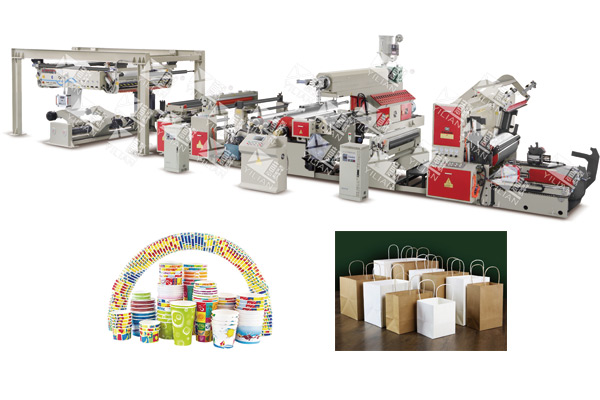
An Extrusion Coating Lamination Machine like the SJFM 1000-2000D double mainframe extrusion film laminating machine runs at 100-150 m/min with coating thicknesses from 0.010-0.1mm and up to four-layer capability. But even the most advanced equipment needs the right diagnostic approach. This guide provides a five-step field-tested process for identifying and fixing coating weight variation—from die bolts to melt pump to air gap—so you can get your line back to uniform production.
Cross-Web or Machine Direction — Diagnose the Pattern First
Before you touch any adjustment, understand what kind of variation you’re dealing with.
Cross-Web Variation (CD)
Cross-web variation means the coating is thicker on one side than the other, or thick in the middle and thin at the edges. This type of variation is usually caused by die lip gap issues, temperature non-uniformity across the die, or air flow disturbances at the edges.
Machine-Direction Variation (MD)
Machine-direction variation appears as periodic thick-thin stripes along the length of the web. This is almost always caused by output fluctuations—from the melt pump, extruder, or substrate tension variations. A pulsating melt flow creates a pattern that repeats at regular intervals.
The Diagnostic Test
The simplest way to distinguish between CD and MD variation: stop the line, take samples across the web width at five points, then take additional samples along the machine direction at ten points. Weigh each sample and plot the results. If the variation is primarily across the width, focus on die and temperature adjustments. If the variation is along the length, focus on melt pump and tension issues. The SJFM series features PLC man-machine interface control, which provides real-time data on line speed and other parameters to aid in diagnosis.
Adjusting Die Lip Gap with Thermal Bolts
The die lip gap determines the flow rate of molten polymer across the web width. Each thermal adjustment bolt controls a localized section of the die lip.
The Right Adjustment Direction
A common misconception: tightening a bolt increases flow. In reality, tightening the bolt pushes the lip closed, reducing the gap and decreasing flow in that area. If a section of the web is too thick, tighten the corresponding bolt to restrict flow. If a section is too thin, loosen the bolt to open the gap and increase flow.
The 1/8 Turn Rule
Make adjustments in small increments—1/8 turn at a time. After each adjustment, wait 15 minutes for the melt to stabilize before taking a new sample. Rushing the process leads to over-correction and new problems. The SJFM series uses a high-precision mould die, which responds predictably to bolt adjustments.
Document Your Adjustments
Keep a log of which bolts were adjusted and by how much. Over time, this log becomes a valuable reference for setting up similar jobs and identifying recurring issues.
Checking Melt Pump Suction and Discharge
If the variation is in the machine direction, the melt pump is the first place to look.
Inlet Blockage
A partially blocked melt pump inlet—from degraded polymer or contamination—causes the pump to cavitate. The result is a pulsating flow that creates MD stripes. Check the pump inlet pressure. If it‘s below 3 bar, the pump is starving for material.
Clogged Screen Pack
A clogged screen pack creates back-pressure fluctuations that translate into flow variations. The SJFM series features a fast-exchange filter screen design, allowing operators to change screens quickly with minimal downtime. If MD variation appears, check the screen pack pressure differential and replace the screen if the differential has increased significantly from baseline.
Gear Pump Synchronization
If your line uses a gear pump for precise melt delivery, verify that the pump speed is synchronized with the extruder screw speed. A mismatch creates beat frequencies that appear as MD thickness variation.
Air Gap and Edge Encapsulation
The air gap—the distance between the die lip and the nip—affects how the melt spreads across the web.
Edge Turbulence
If the coating is significantly thinner at the edges than in the center, edge air turbulence is the likely culprit. Air currents at the edges disturb the melt curtain, reducing the amount of polymer that reaches the substrate at the edges.
Install Air Shields
Adding air shields (also called air bars or edge encapsulators) at the die edges stabilizes the melt curtain and reduces edge thinning. If air shields are already installed, check that they are clean and properly positioned. The SJFM series is designed with integrated unwinding and rewinding, drying, surface treatment, extrusion, compounding, trimming, and suction, and edge trimming helps manage edge effects.
Reduce the Air Gap
If air shields aren‘t available, try reducing the air gap to 60mm or less. A shorter gap reduces the distance the melt must travel through the air, minimizing the opportunity for edge turbulence to affect the melt curtain.
Temperature Uniformity Across the Die
Temperature variations across the die width create viscosity variations, which create flow variations.
The 5°C Rule
Use a surface thermocouple to measure the die body temperature at 100mm intervals across the entire die width. The temperature should not vary by more than 5°C from end to end. A larger variation indicates heater problems that need correction. The SJFM series uses automatic temperature control as part of its advanced technology suite.
Failed or Underperforming Heaters
A failed heater cartridge or a heater with poor contact will create a cold spot in the die. Cold polymer has higher viscosity and flows less, creating a thin spot in the coating. Check the heater resistance and replace any failed units.
PID Controller Tuning
If heaters are functioning but temperature is unstable, check the PID controller settings. Oscillating temperature indicates a tuning issue. Adjust the PID parameters or consult the machine manufacturer for recommended settings.
Substrate Tension Variation
The substrate tension at the nip affects how the melt is compressed and spreads.
Tension Fluctuations Create Coating Variation
If the substrate tension varies, the pressure at the nip varies, and the coating thickness varies. Tension variations are often caused by dirty or misaligned tension sensors, worn dancer rollers, or mechanical issues in the unwind section. The SJFM series features full automatic constant tension control.
Clean and Calibrate Tension Sensors
Tension sensors can accumulate dust and debris, which reduces their sensitivity. Clean the sensors according to the manufacturer‘s instructions, then recalibrate them. A simple cleaning and calibration often resolves subtle tension-related coating variations.
Check Dancer Roller Movement
The dancer roller should move smoothly through its full travel range. A sticking dancer roller creates tension spikes that show up as coating variation. Lubricate the dancer roller bearings and check for any mechanical binding.
Questions Process Engineers Ask About Coating Uniformity
How often should we recalibrate the die bolts?
Recalibrate die bolts after any major die cleaning or when you notice a shift in the coating profile. For most lines, a full recalibration every 3-6 months is sufficient, with spot checks between major jobs. The SJFM series is designed for high-precision operation, making it responsive to proper calibration.
Can the same die be used for 5gsm and 30gsm coating?
Yes, but the die gap and temperature settings will be different. Lighter coatings require a smaller die gap and often lower temperatures to prevent polymer degradation. Heavier coatings need a larger gap and higher temperatures to achieve the required flow. Always run test samples when changing coating weight significantly.
Why does uneven coating appear only after 2 hours of running?
This is a classic symptom of die lip buildup. Over time, degraded polymer accumulates on the die lip, altering the flow profile. The buildup is gradual—it doesn‘t affect the coating immediately, but after a few hours, the flow becomes uneven. Regular die lip cleaning and proper purging practices prevent this issue.
| Variation Type | Likely Cause | First Check |
|---|---|---|
| Thick in center, thin at edges | Die gap or edge air turbulence | Die bolts and air shields |
| Thick on one side only | Uneven die gap or heater failure | Thermal bolts and temperature profile |
| Periodic MD stripes | Melt pump pulsation or screen pack clog | Pump inlet pressure and screen pack |
| Random MD variation | Substrate tension fluctuation | Tension sensors and dancer roller |
| Appears after 2+ hours | Die lip buildup | Clean die lip |
Creating a Coating Profile Map
A coating profile map is the single most useful tool for maintaining coating uniformity over time.
H3: The Bi-Weekly Profile
Every two weeks, run a full-width multiple-point coating weight measurement. Take samples at five or more points across the web width and weigh each sample. Plot the results on a graph. A profile map shows you the current coating distribution and allows you to spot trends before they become problems.
Track the Trend
If the profile is consistently changing in the same direction, you have a systematic issue—die wear, heater degradation, or a recurring process problem. Use the profile map to guide maintenance decisions and to validate that adjustments have the intended effect.
Share with Your Team
Make the profile map visible to the entire production team. When operators see the data, they understand the impact of their adjustments and become partners in maintaining coating uniformity. The SJFM series‘ PLC control system can store and recall process parameters, making it easier to reproduce successful profiles.
Request a Coating Profile Audit for Your Line
Uneven coating weight on an extrusion coating lamination line is one of the most solvable—yet most persistent—quality issues. The key is a systematic approach: diagnose whether the variation is cross-web or machine-direction, adjust die bolts in small increments, check melt pump performance, address edge air turbulence, verify temperature uniformity, and stabilize substrate tension.
Winrich Machinery manufactures the SJFM series of environmentally friendly extrusion lamination machines, featuring integrated unwinding, drying, surface treatment, extrusion, compounding, trimming, and suction. The SJFM 1000-2000D double mainframe extrusion film laminating machine runs at 100-150 m/min with 500-1750mm net laminating width and coating thickness from 0.010-0.1mm. It processes paper, plastic film, non-woven fabrics, and aluminum foil into two-layer, three-layer, or multi-layer composites for food, pharmaceutical, and industrial packaging.
Contact Winrich Machinery‘s technical team — they can provide remote diagnostics, on-site support, and a customized coating profile improvement plan for your specific line configuration.